
I decided to start a new project log in hopes that this will make me more motivated to work on and finish up this project.
I'm going to be converting every Incandescent light in my car over to LED (except for the headlights which have an HID retro). Doesn't matter what the bulb is or where it is I will be converting it to LED if possible.
Let's start with what I've already completed, which isn't much.
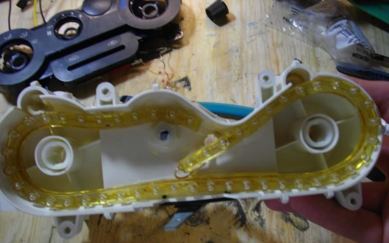
I did a quick and dirty LED conversion on my HVAC controls with some flexible LED strip. However depending on how Soundman's HVAC controls turn out I might change these over to Superflux.
LED strip glued in place.
![Image]()
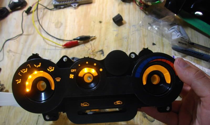
Lit up without the knobs installed.
![Image]()
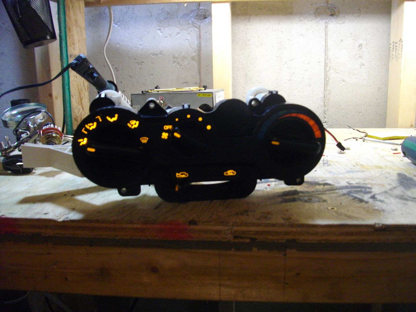
All back together.
![Image]()
I'm going to do my S2000 cluster but there's a company called Qube Engineering that makes new LED boards so it so I'm going the easy route and buying that.
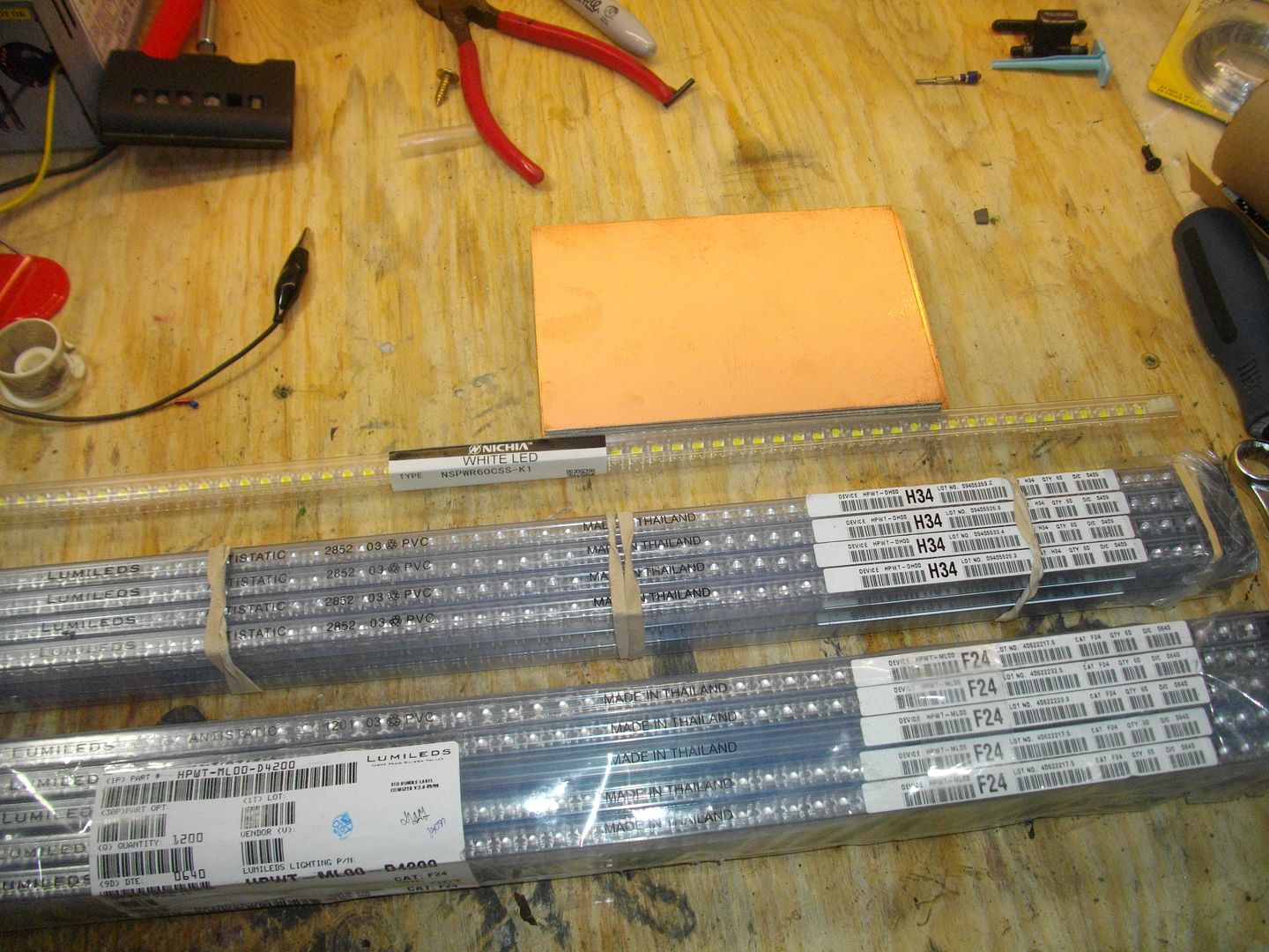
I'm using all Lumileds with the exception of one tube of Nichia for my dome lights, license plate lights, trunk lights, glove box light and under dash lights.
Lumiled HPWT-DH00-G4000 H34 bin - 700 pieces
Lumiled HPWT-ML00-D4200 F24 bin - 1200 pieces
Nichia NSPWR60CSS-K1 C0 bin - 60 pieces
My Lumileds were bought from eBay as NOS items and my Nichia's came straight from Nichia Japan (via Nichia USA).
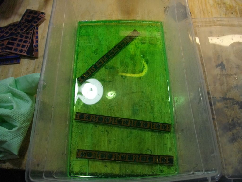
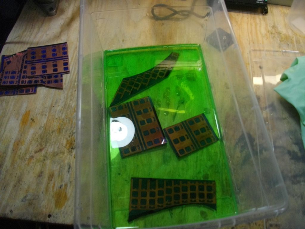
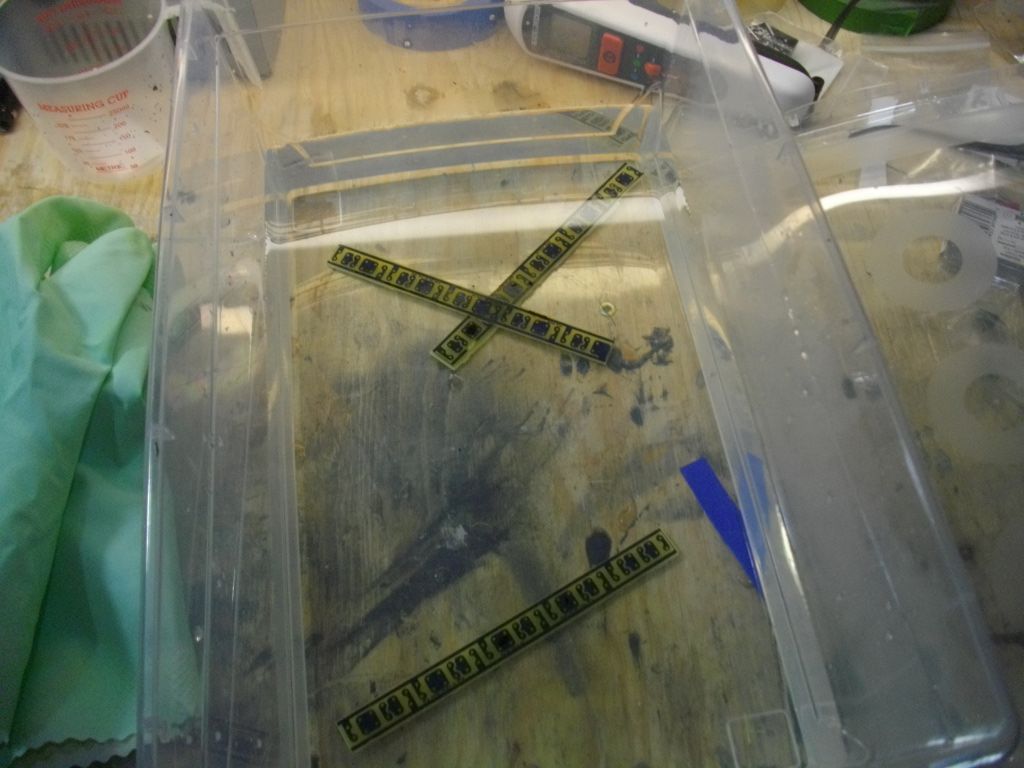
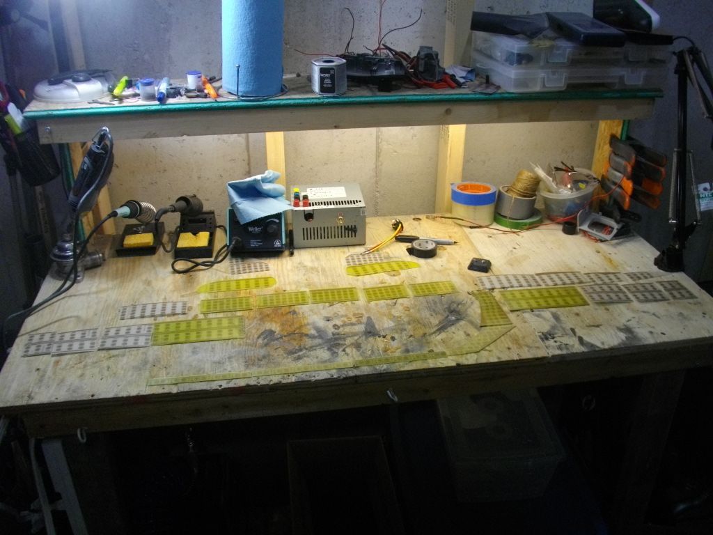
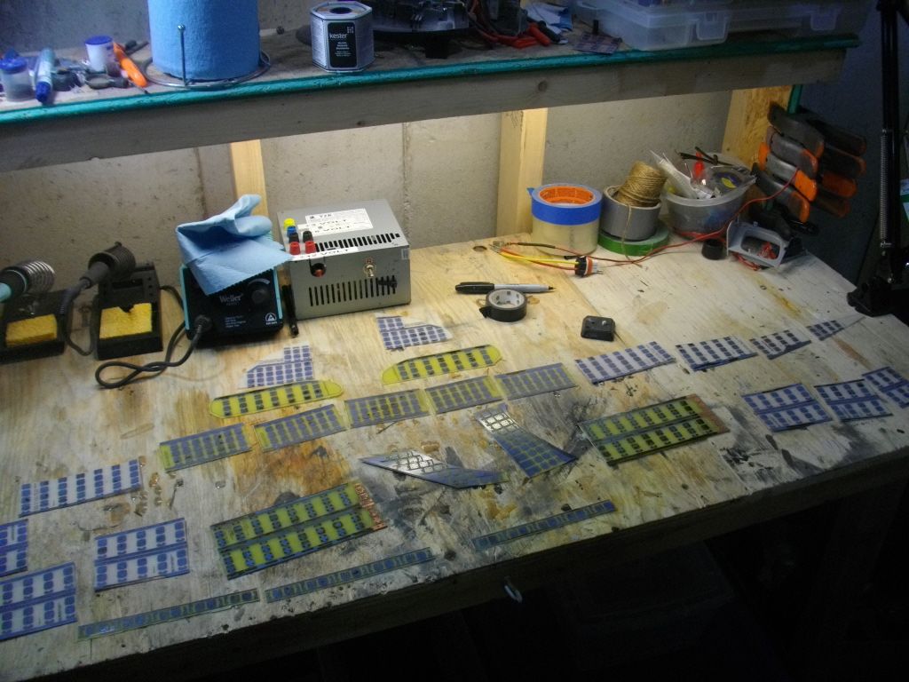
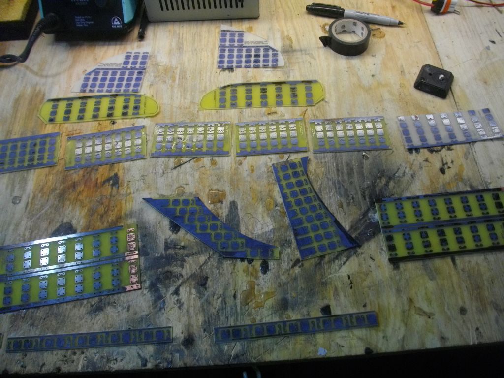
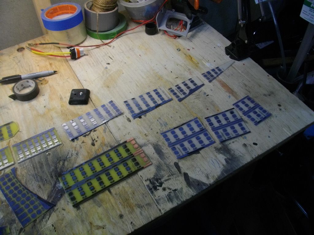
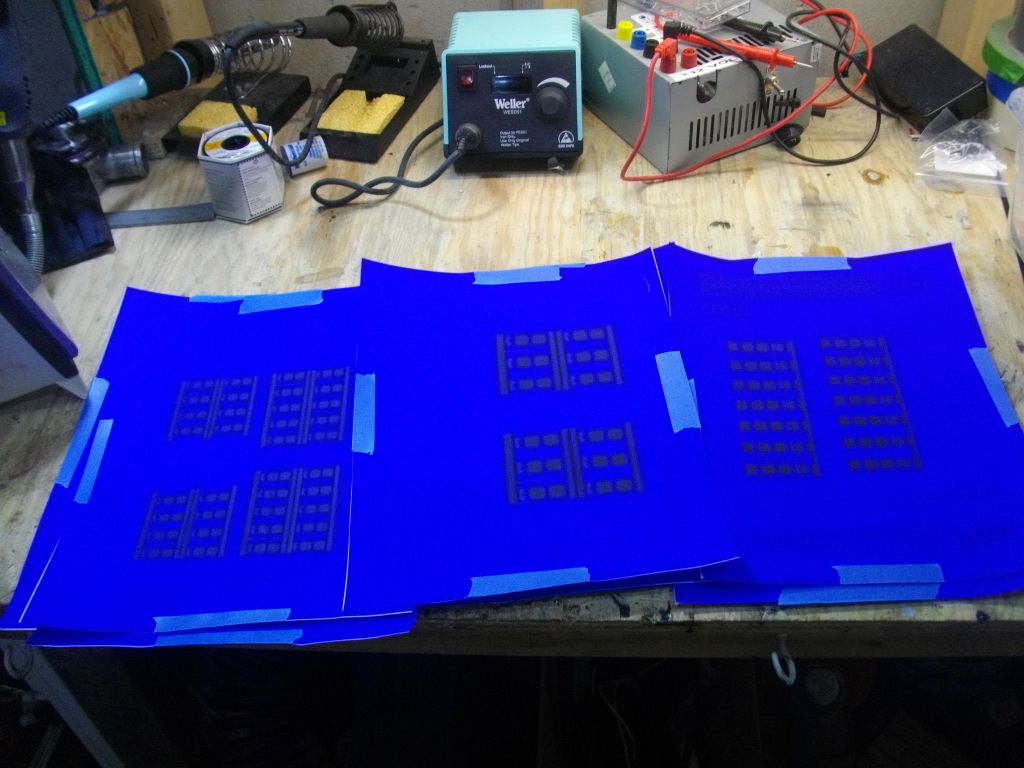
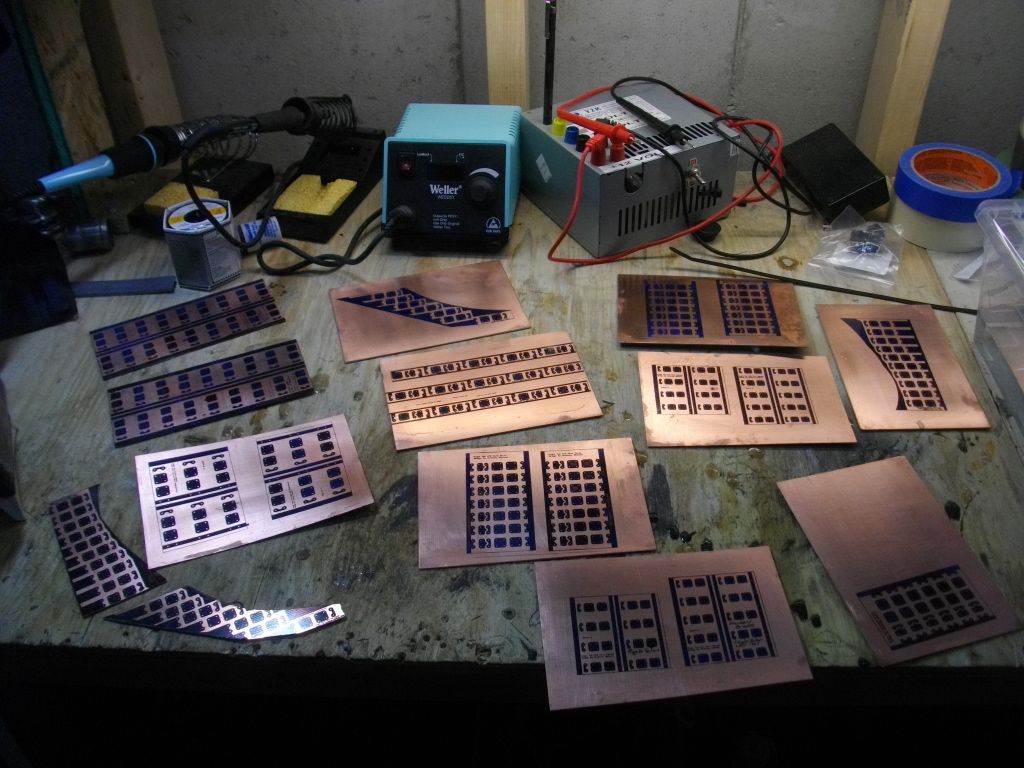
Here's the collection of LEDs and my copper clad board for etching my own boards.
![Image]()
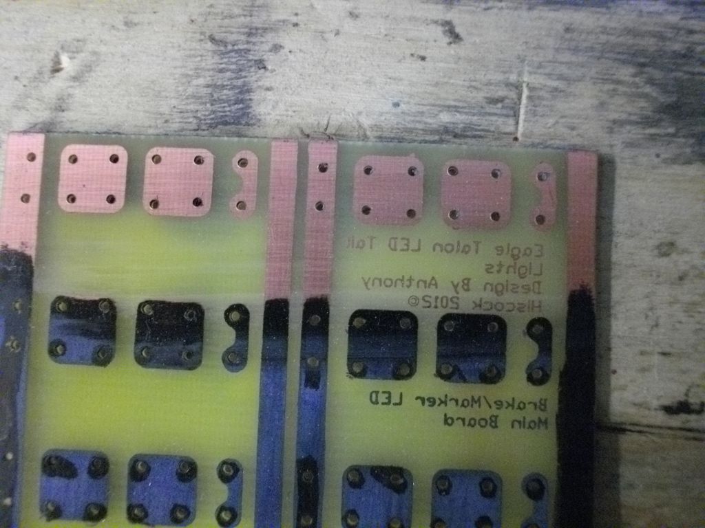
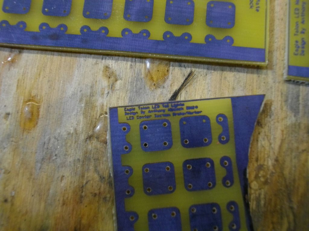
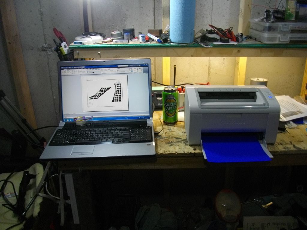
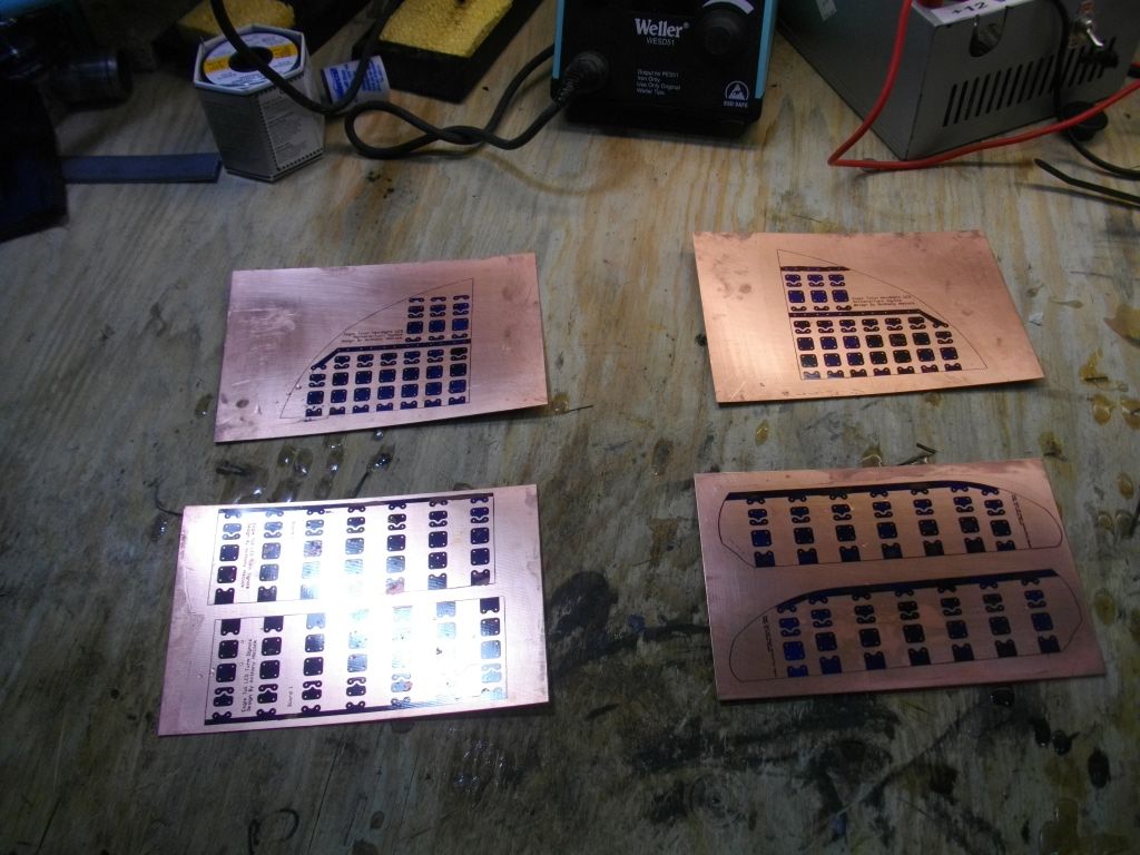
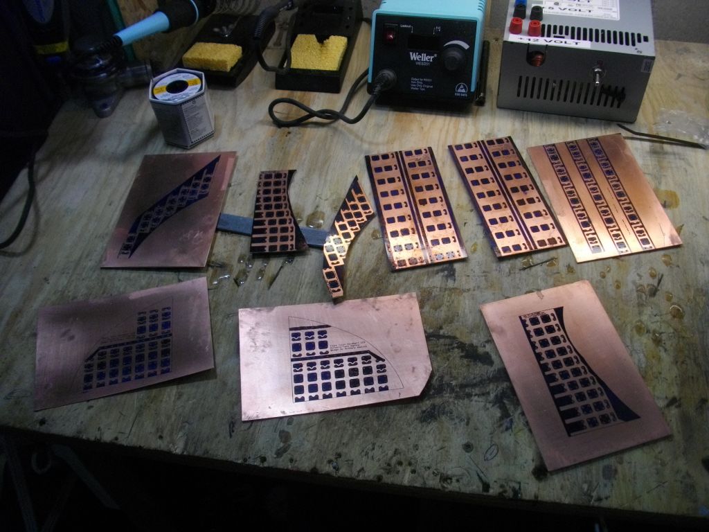
I've progress out of the planning stages (with the exception of my center tail light) and I'm slowly moving forward in board design with Eagle PCB.
Interior lights don't really need to be discussed as they are pretty basic so I'll just talk about my exterior ones instead.
I'll start with my front turn signals and bumper lights. These will be marker and turn (bumper lights are marker only from the factory) and they will be Sequential via a micro controller.
Rear turn signals will be signal only and sequential too.
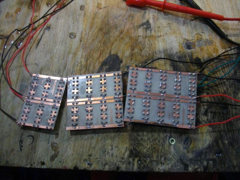
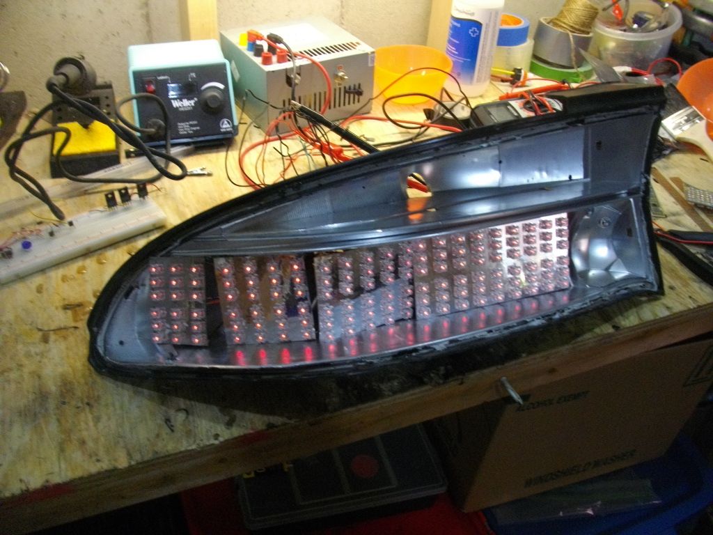
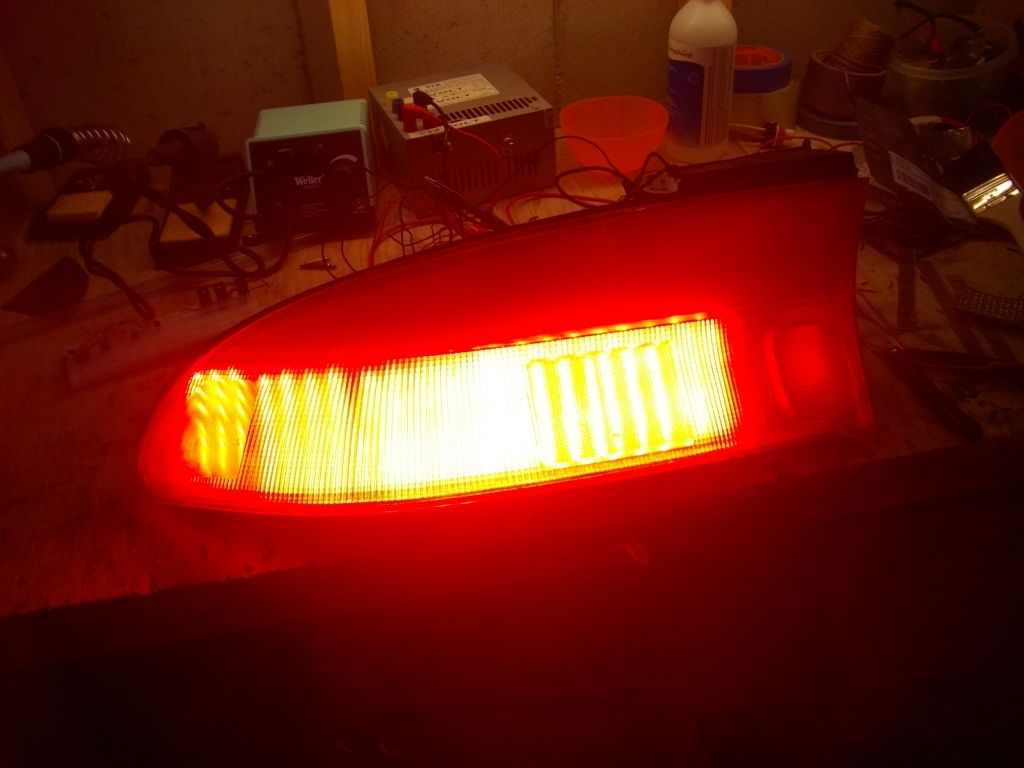
My brake lights will marker and turn plus I'm going to attempt to convert the center portion to LED so it lights up too, the center does not light up from the factory.
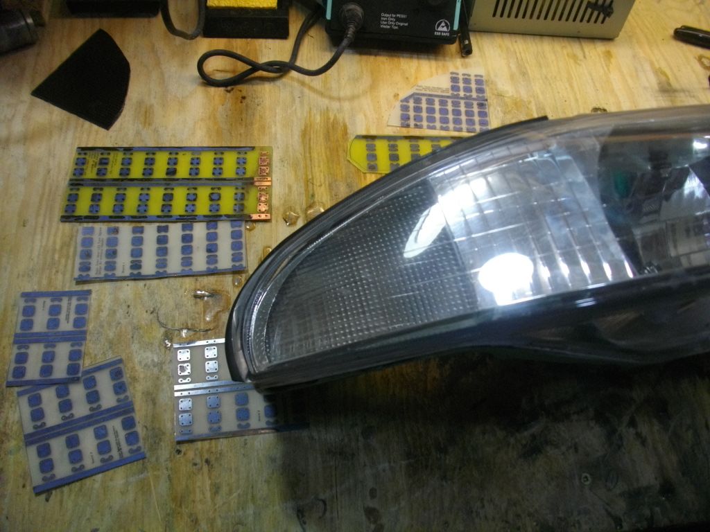
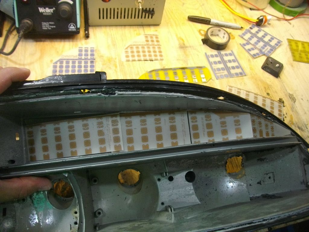
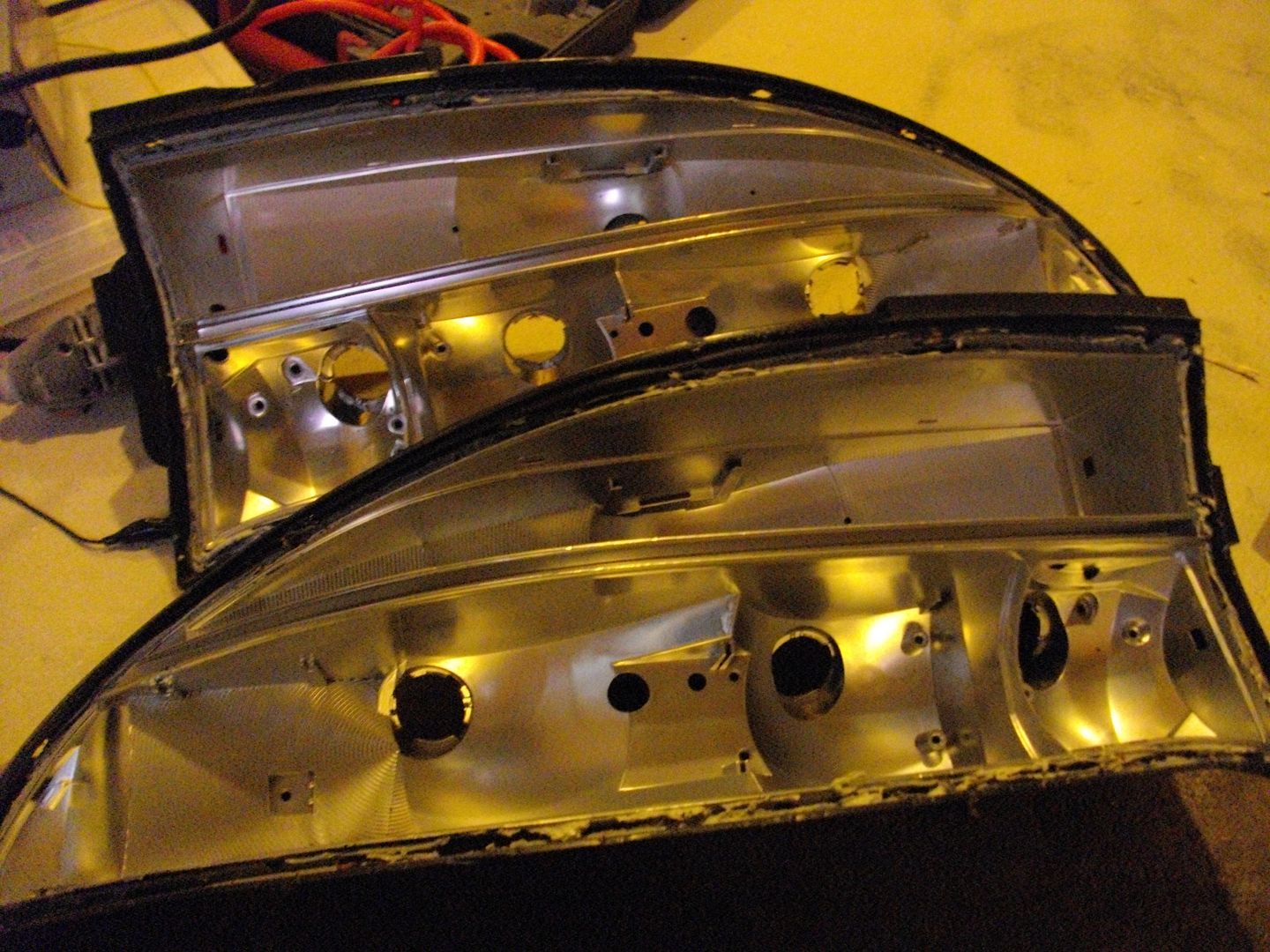
Here's both my left and right tail lights stripped down.
![Image]()
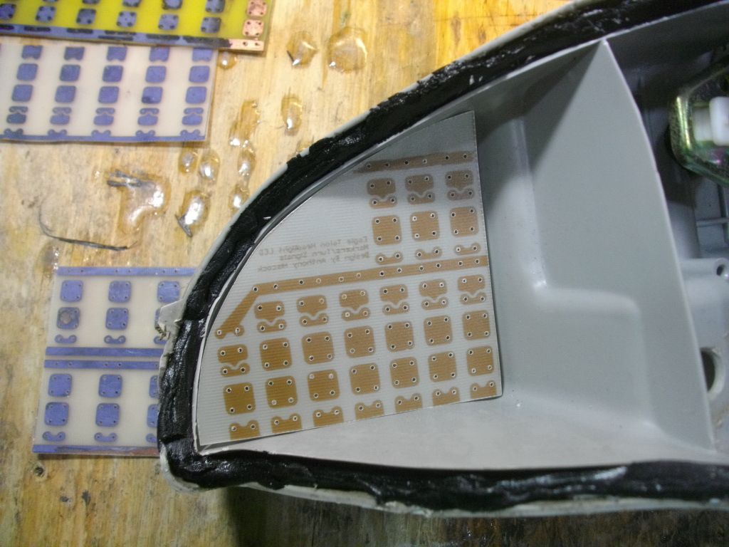
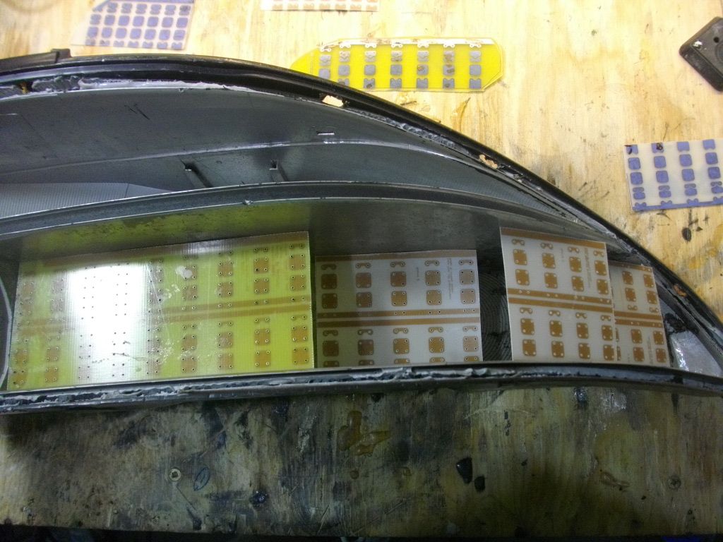
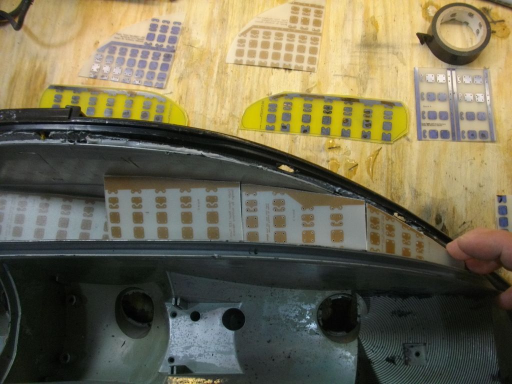
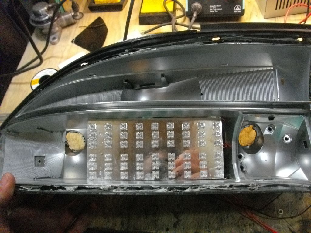
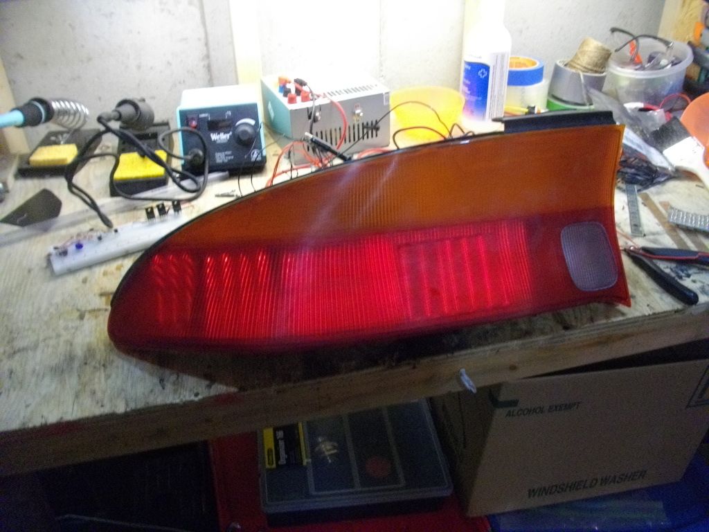
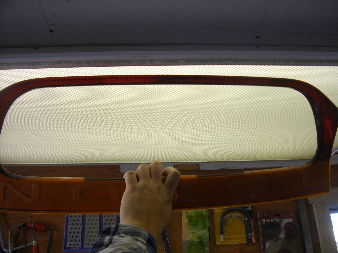
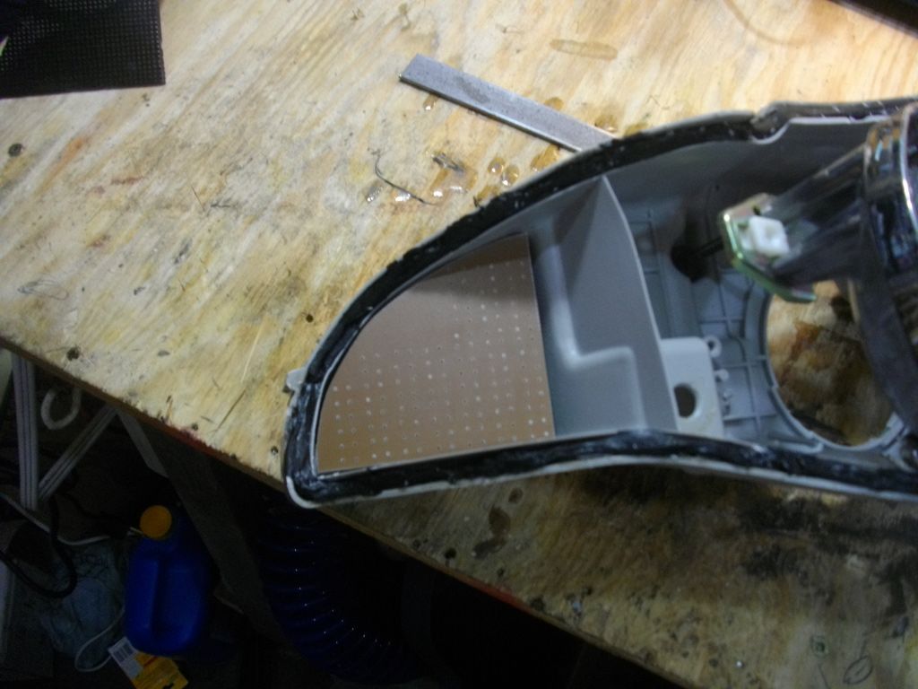
The center section is painted from the factory with an opaque silver paint (in the following photo you can see some of it is removed already).
![Image]()
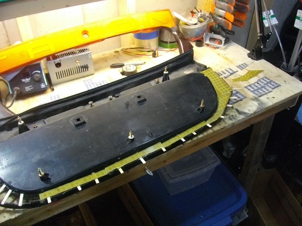
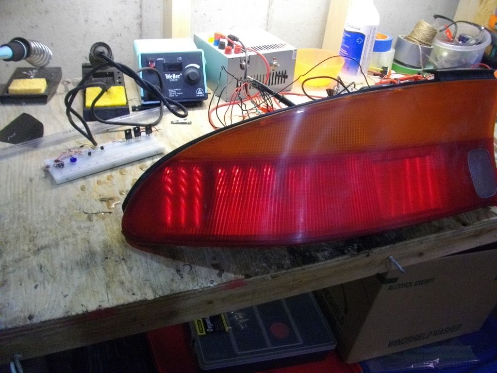
I used my cheap home made soda blaster and cleaned it all out, I still need to work on it a bit more but it will work for testing purposes.
![Image]()
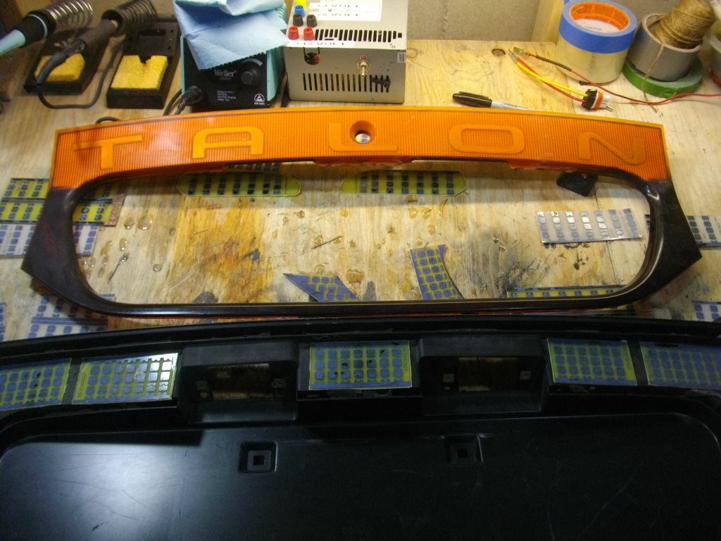
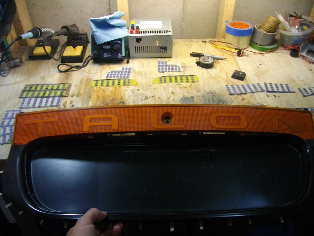
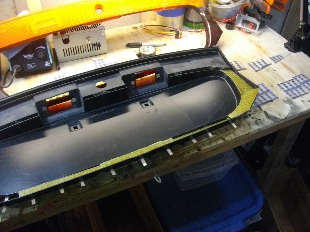
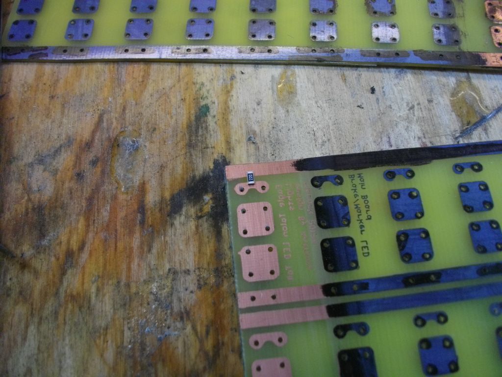
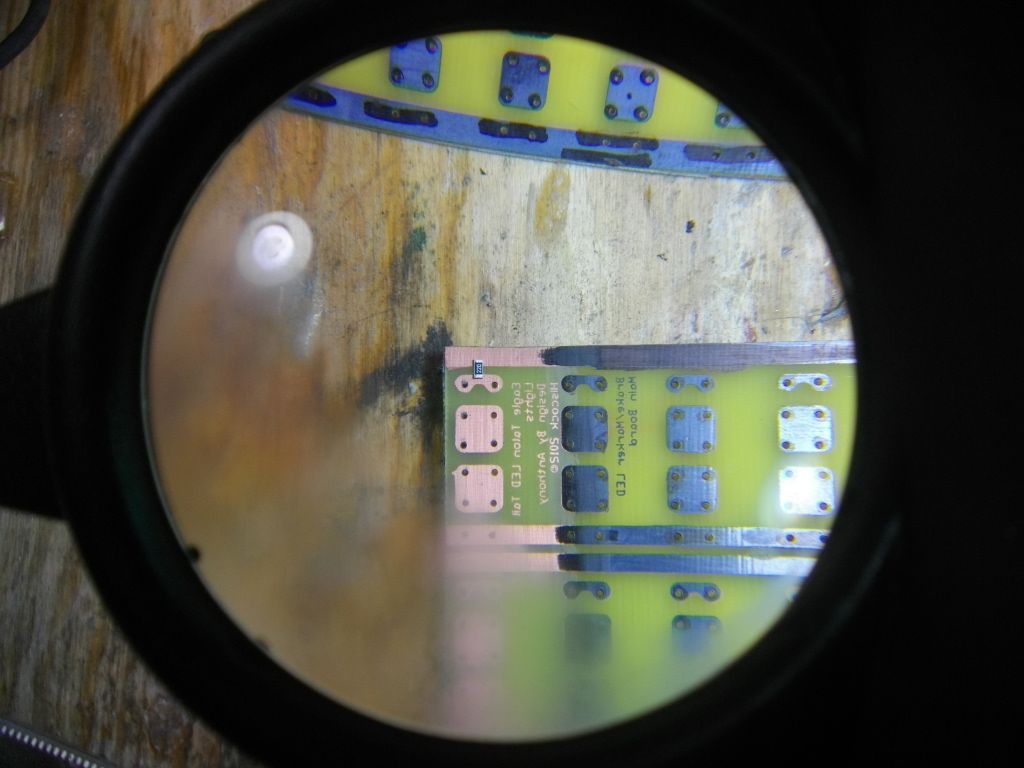
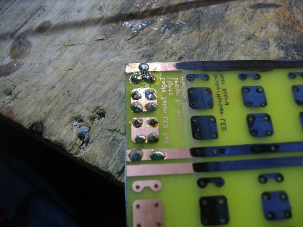
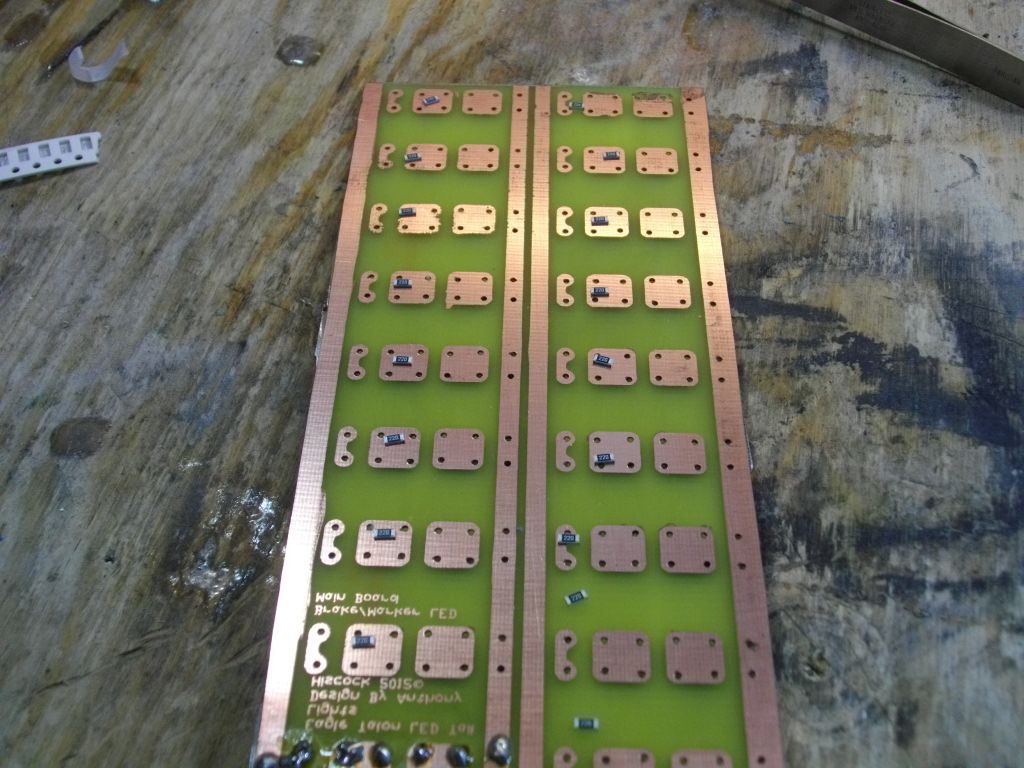
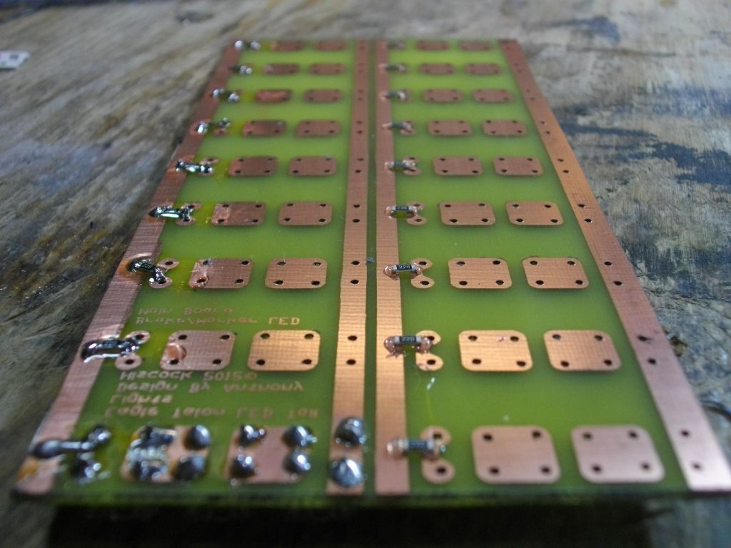
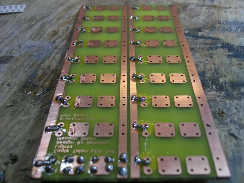
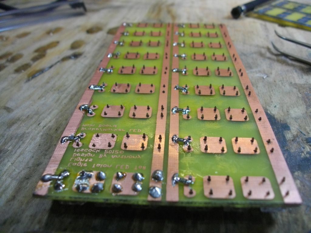
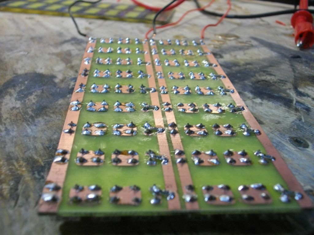
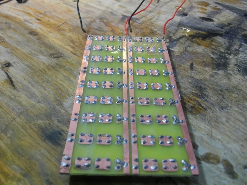
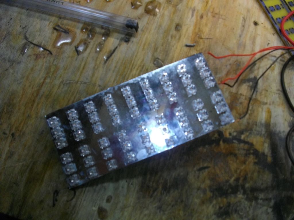
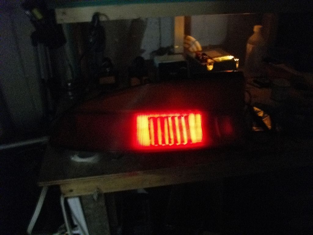
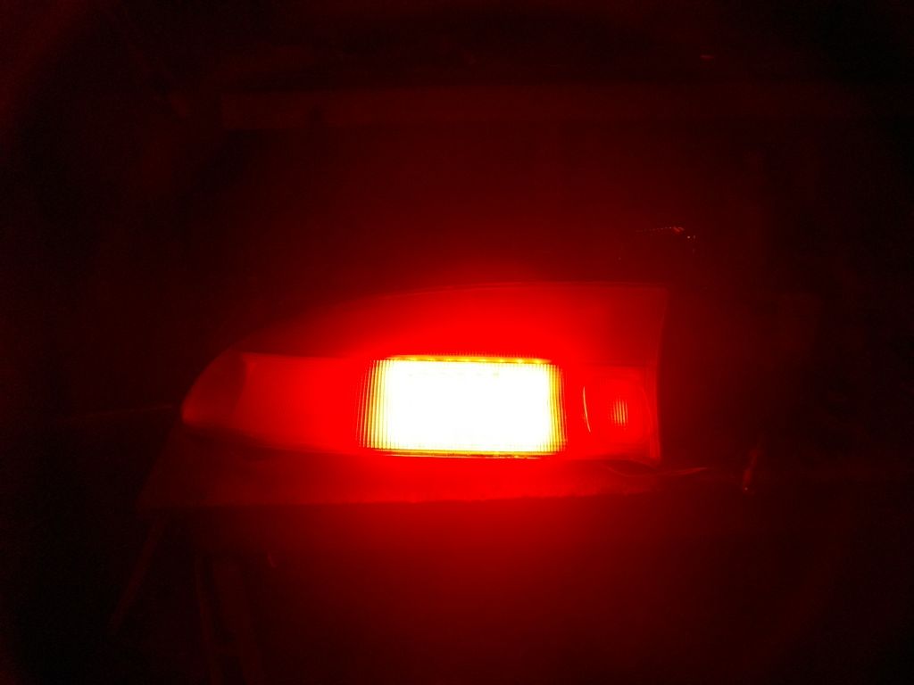
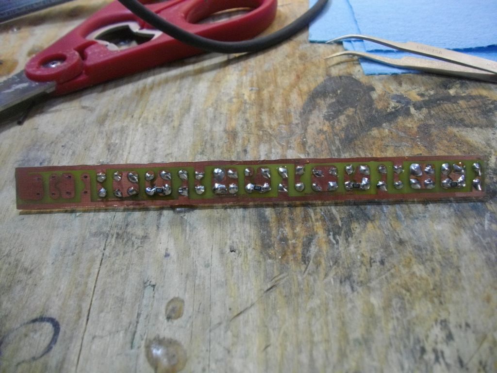
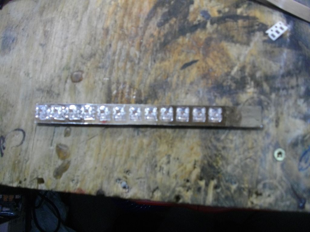
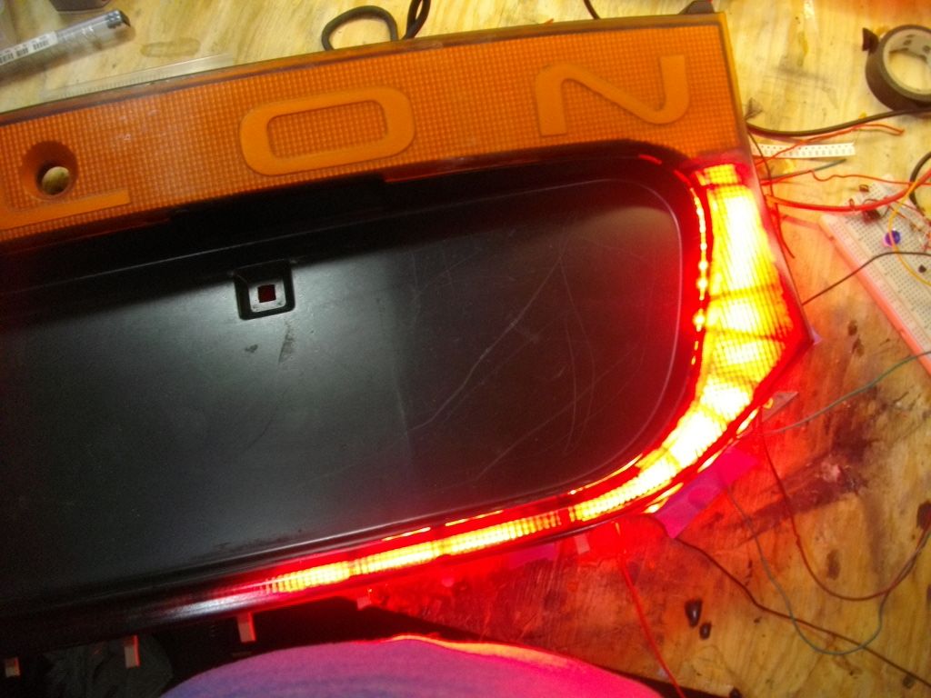
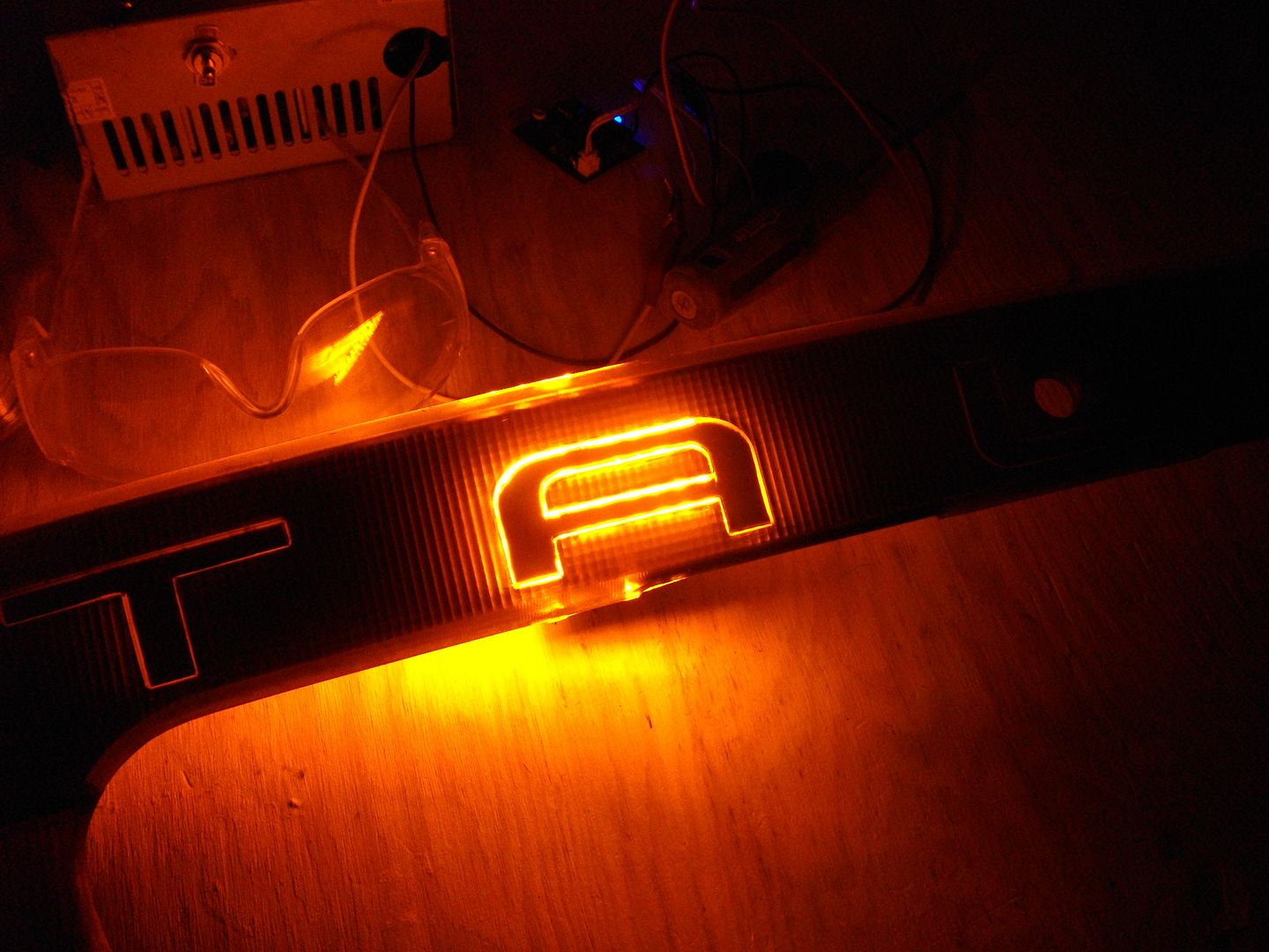
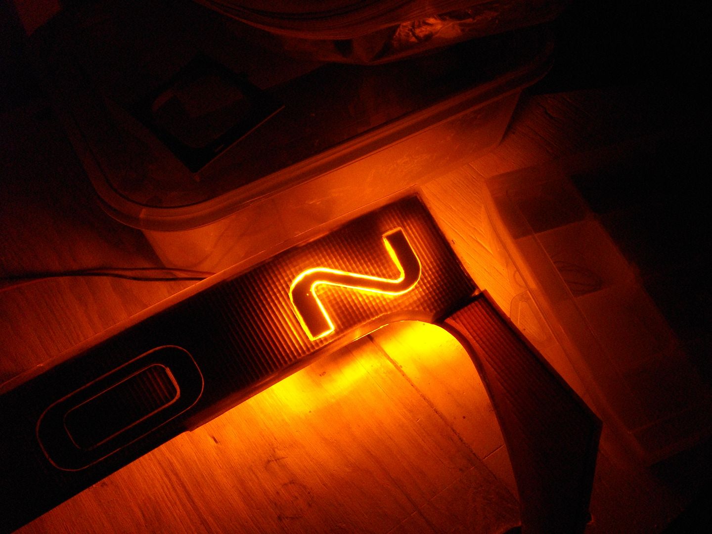
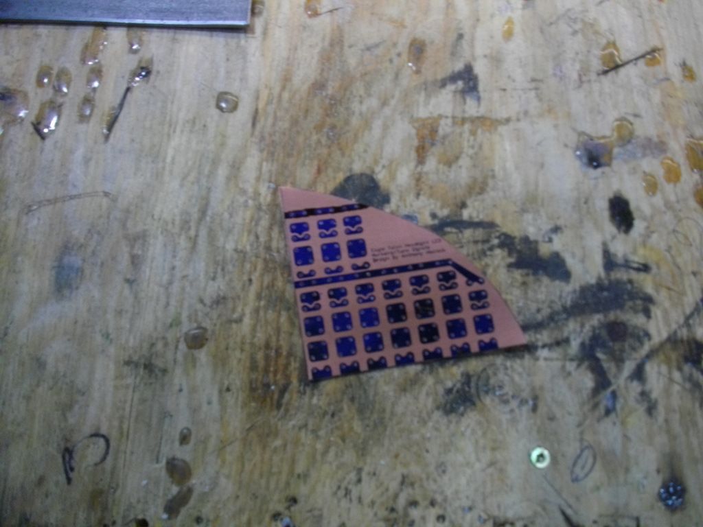
I'm also going to build an LED board to redo my light up name plate on the tails. Here's a little teaser of how it looks so much better then the LED strip that was in there.
![Image]()
![Image]()
I'm going to be converting every Incandescent light in my car over to LED (except for the headlights which have an HID retro). Doesn't matter what the bulb is or where it is I will be converting it to LED if possible.
Let's start with what I've already completed, which isn't much.
I did a quick and dirty LED conversion on my HVAC controls with some flexible LED strip. However depending on how Soundman's HVAC controls turn out I might change these over to Superflux.
LED strip glued in place.
Lit up without the knobs installed.
All back together.
I'm going to do my S2000 cluster but there's a company called Qube Engineering that makes new LED boards so it so I'm going the easy route and buying that.
I'm using all Lumileds with the exception of one tube of Nichia for my dome lights, license plate lights, trunk lights, glove box light and under dash lights.
Lumiled HPWT-DH00-G4000 H34 bin - 700 pieces
Lumiled HPWT-ML00-D4200 F24 bin - 1200 pieces
Nichia NSPWR60CSS-K1 C0 bin - 60 pieces
My Lumileds were bought from eBay as NOS items and my Nichia's came straight from Nichia Japan (via Nichia USA).
Here's the collection of LEDs and my copper clad board for etching my own boards.
I've progress out of the planning stages (with the exception of my center tail light) and I'm slowly moving forward in board design with Eagle PCB.
Interior lights don't really need to be discussed as they are pretty basic so I'll just talk about my exterior ones instead.
I'll start with my front turn signals and bumper lights. These will be marker and turn (bumper lights are marker only from the factory) and they will be Sequential via a micro controller.
Rear turn signals will be signal only and sequential too.
My brake lights will marker and turn plus I'm going to attempt to convert the center portion to LED so it lights up too, the center does not light up from the factory.
Here's both my left and right tail lights stripped down.
The center section is painted from the factory with an opaque silver paint (in the following photo you can see some of it is removed already).
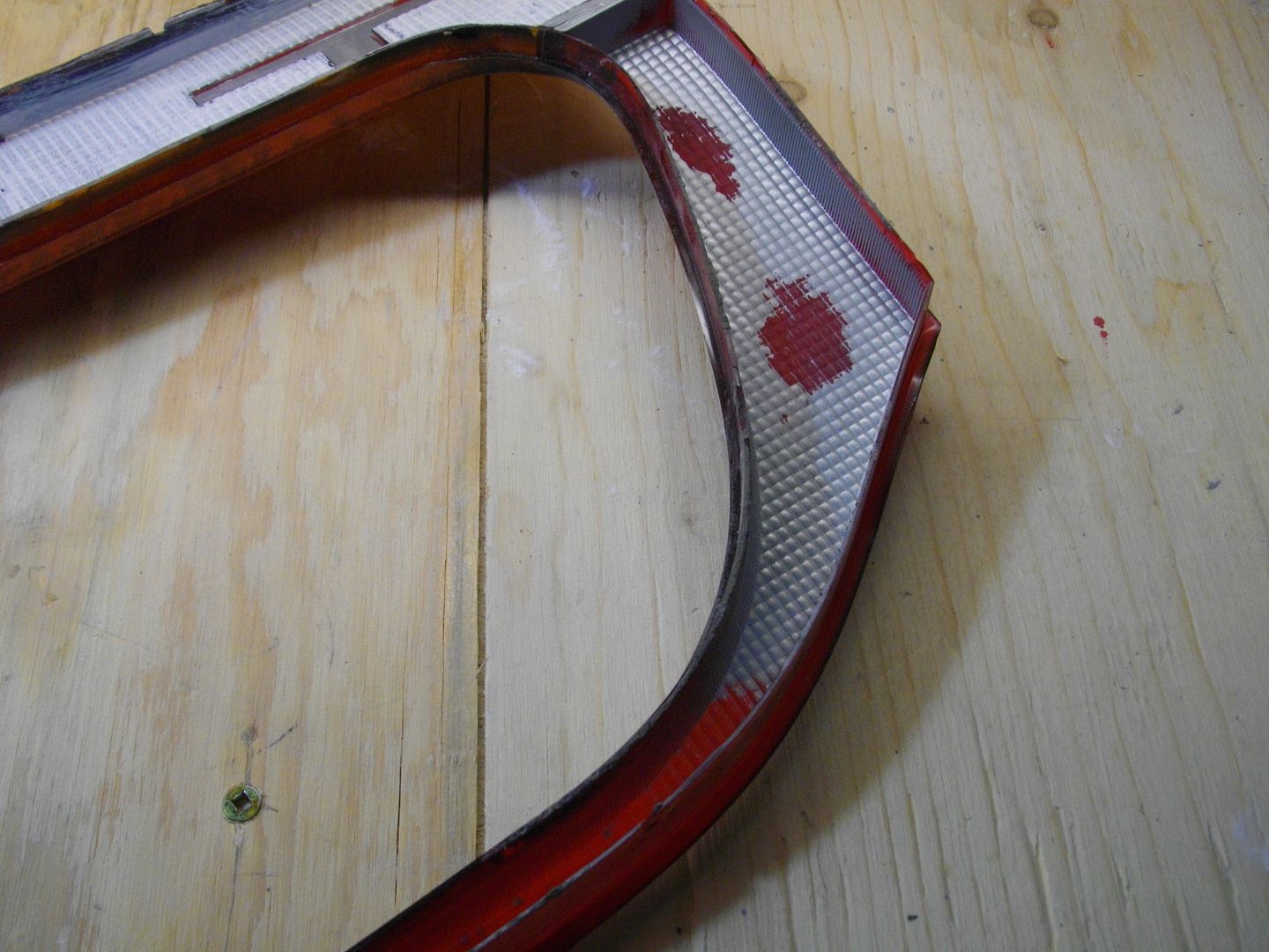
I used my cheap home made soda blaster and cleaned it all out, I still need to work on it a bit more but it will work for testing purposes.
I'm also going to build an LED board to redo my light up name plate on the tails. Here's a little teaser of how it looks so much better then the LED strip that was in there.
") Great work!
Great work!